Checklist for Siphonic Roof Drainage
Every Pipework has to fulfil the following 10 rules:
1. Downpipe
2. Vertical connection pipe
3. Start-up requirement
4. Pressure loss Calculation
5. Vacuum (static pressure)
6. Minimum flow velocity
7. Flow velocity in the transition area
8. Drainage capacity of roof outlets
9. Distance between the roof outlets
10. Drainage capacity in the planning stage
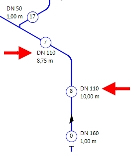
Commandment 1: Downpipe
In Siphonic Roof Drainage the diameter of the downpipe shall be same or smaller than the adjacent collecting pipe.
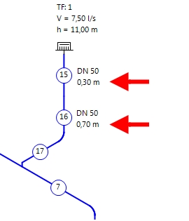
Commandment 2: Vertical connection pipe
VDI 3806 – The diameter of the vertical connection pipe may be larger or smaller than the diameter of the vertical roof outlet spigot.
BS 8490:2007 – The diameter of the vertical connection pipe must not be larger than the diameter of the vertical roof outlet spigot.
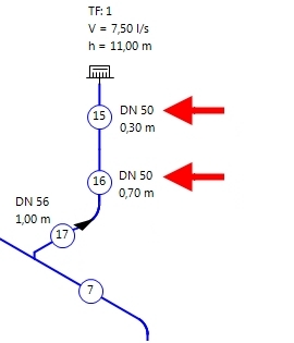
BS 8490:2007.
Commandment 3: Start-Up Requirement
The calculation of the start-up requirement must be carried out at start-up height of < 100cm.
Commandment 4: Pressure Loss Calculation
In the planning stage of a siphonic roof drainge pipework, the variation between available pressure and pressure loss must be +- 100mbar.
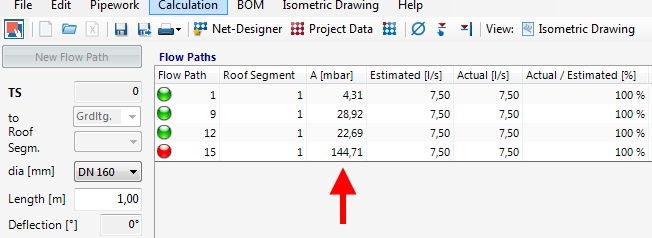
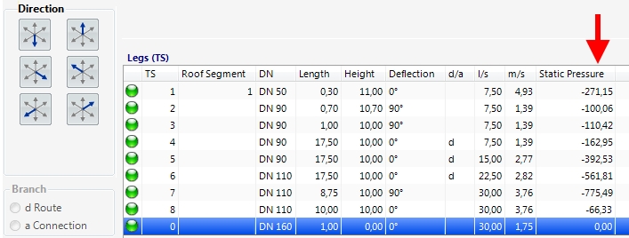
Commandment 5: Vacuum (Static Pressure) in Siphonic Roof Drainage
In the hydraulic calculations, the vacuum pressure must not be less than -900mbar. The operating pressure limits of the pipe system must be taken into account.
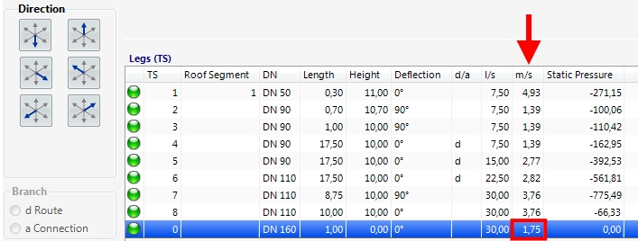
Commandment 6: Minimum flow velocity
Flow velocity of at least 0.7m/s is required according to VDI 3806!

Commadment 7: Velocity of flow in the transition area
In the transition area from a siphonic system to an open drainage system, the flow velocity must not be higher than 2.5m/s.
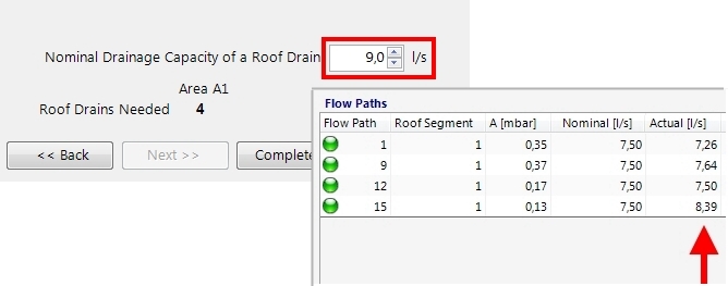
Commandment 8: The drainage capacity of the roof outlet
The drainage capacity of the roof outlet in Siphonic Roof Drainage must not be selected as greater than the maximum drainage capacity of the relevant roof outlet.
Commandment 9: Distance between the roof outlets
The distance between the roof outlets in a shared drainage axis must not exceed 20 meters.
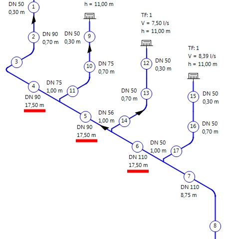
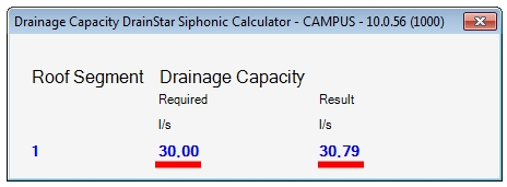
Commandment 10: Drainage capacity in the planning stage
In the planning stage of Siphonic Roof Drainage pipework, the effective drainage capacity of all the outlets allocated to a roof surface or roof segment is not allowed to fall short of the nominal drainage required by the calculation.
Closing words
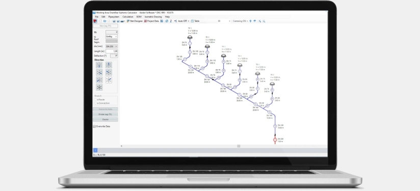
At the end of this blog I would like to ask all designers to follow and apply these 10 commandments. It should be second nature to you, as it is to any airplane pilot. There are other important rules, tips and tricks that I will come back to in other blogs. The examples in this blog were created using Keidel’s DrainStar® Siphonic Calculator, the compact software for sizing siphonic roof drainage.
DISCLAIMER – This Information is based on German laws, standards, and regulations (rules). We shall give no guarantee that the information is suitable for use in other countries or that it is in accordance with the rules in place there. Nevertheless, we are unable to guarantee the correctness, completeness and up-to-dateness of the information and therefore exclude any liability in this respect. Subject to change without notice. © Keidel DrainStar GmbH. All rights reserved. V 2110